Motoplat ignition information
Get your motoplat rebuilt!
You can have your motoplat system repaired and rebuilt. These services are
to be found at the following places:
Pekka Förbom (Finland), pekka.forbom@postikaista.net
Charges between 100 and 130 euro depending on the work. He has the machinery
to
rewind the coils. He repairs both motoplat and SEM systems.
Vintage Dirt Bike (USA), www.vintagedirtbike.com
All electronic ignition models
$195 complete, 6 month warranty, quick turn around
Phone: (832) 788-5306 FAX: (270) 588-5627
Stator Rewinds (Australia), http://www.dropbears.com/r/rewinds/
All motorcycle stators rewound
to factory specs or better.
Phone: +61 (0)243 692 313
Fax: +61 (0)243 692 313
motoplat system
Most older bikes have a ignition system and possibly a lightning named motoplat.
Motoplat was a spanish company and supplied numerous manufacturers with ignition
systems. Not only for MX and enduro bikes but also karting and road bikes. At
least the european bikes where almost always equipped with the motoplat systems.
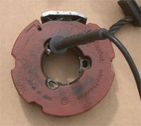
These can easily be identified by their red plastic encapsulated stators and
coils. Bikes like KTM, Penton, Maico, Ossa and Husqvarna are likely equipped
with these.
Internal and external flywheel
 There
are basically two types of ignition systems. First the internal flywheel type.
These doesn't have lightning coils and is mostly common on motocross bikes.
The smaller diameter flywheel was supposed to make the engine revier with quicker
response. Consequently the idle and low rev, trail properties are worse. The
external rotor (flywheel) sometimes has lightning coils. The larger diameter
places most of the rotating mass further out and therefore makes the engine
more stable at lower revs. It also build revs slower and is therefore more suitable
in enduro applications. Another negative effect is that the larger rotating
mass adds a gyroscopic effect to the rotating engine which makes the bike harder
to lean down in turns. This is a somewhat odd physical thing that easiest can
be explored with a plain hand grinding machine
There
are basically two types of ignition systems. First the internal flywheel type.
These doesn't have lightning coils and is mostly common on motocross bikes.
The smaller diameter flywheel was supposed to make the engine revier with quicker
response. Consequently the idle and low rev, trail properties are worse. The
external rotor (flywheel) sometimes has lightning coils. The larger diameter
places most of the rotating mass further out and therefore makes the engine
more stable at lower revs. It also build revs slower and is therefore more suitable
in enduro applications. Another negative effect is that the larger rotating
mass adds a gyroscopic effect to the rotating engine which makes the bike harder
to lean down in turns. This is a somewhat odd physical thing that easiest can
be explored with a plain hand grinding machine 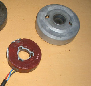 rotating
in your hands. While it does so, try to flick it sideways and you will feel
what the gyroscopic effect will do. Basically what it's all about is that once
a moving force is applied onto a rotating body the outcoming movement will be
in 90 degrees from the applied forces direction.
rotating
in your hands. While it does so, try to flick it sideways and you will feel
what the gyroscopic effect will do. Basically what it's all about is that once
a moving force is applied onto a rotating body the outcoming movement will be
in 90 degrees from the applied forces direction.
The external rotor comes in a few different types as well. The most common
one has a small pin on the front side that is supposed to fit into a groove
inside the flywheel. It's mounted by three small screws on the inside near the
crank shaft. The outer diameter is about ø83mm. The inside of the flywheel
is ø85mm. The other type is mounted the same way. Doesn't have a pin
on the face but one of the coils has a larger metal plate surrounding it, it
looks like a pickup. The outer diameter is slightly larger. Just about ø85mm.
It will therefore not fit into the other types flywheel. There is also a smaller
type seen on smaller displacement engines, like the sachs 100-175cc for example.
The three mounting screws is located outside the entire stator plate.
Ignition coil connection
All motoplat stators have a black and a blue wire. The blue wire has a larger
connection whereas the black is smaller. These are intended for the ignition
coil. The blue is the capacitor charge and is mostly lengthened so it can be
connected to a kill switch. The black wire is the trigger wire for the coil,
triggering the actual spark. If there there is no kill switch you can connect
a wire to the blue wire and to a kill switch.
Testing the stator ignition
There are two basic types of stators. One with the diode in the stator. This
diode is replacable and is usually connected to a ignition coil that has a black
lead to the spark plug. It can be identified by having a diode symbol on the
stator.
Testing the stator with a diode.
Disconnect both the black and the blue wire from the ignition coil and kill
switch. Connect one test lead to ground and the other to the blue wire. Interchange
the two test leads and read the results. In one direction there should be infinity
and the other there should be a very high resistance. between 3000 and 9000
ohms. If none of the measurements shows infinity the diode is defective. This
is almost always combined with a significantly lower resistance, below 100 ohms.
If on the other hand one direction shows infinity but the other a very high
reading, well over 10000 ohms the stator itself is interrupted but the diode
is good.
Testing the stator without the diode
Disconnect both the black and blue wire from the ignition coil and kill switch.
Take a measure between ground and the blue wire. There should be a reading between
140 and 200 ohms shows that the charging coil is good. Now measure between the
blue and black wire. There should be a reading between 16 and 24 ohms. If there
is a short in the coil you will get a reading under 15 ohms.
Testing the ignition coil
The ignition coil with the black spark plug lead can be tested with an ohmeter.
Take a measurement between ground and the large terminal, the one that should
be connected to the blue wire. You should get brief reading and then immidiately
to infinity. Interchange the test leads a few times and check that the reading
within a short moment returns to infinity every time. The secondary winding
can be tested by measuring the resistance between ground and the spark plug
wire. The value should be within 7000 to 9000 ohms.
The coil with the red spark plug lead, the one with a diode cannot be tested
except for the secondary winding that should be tested exactly as the other
one with the black spark plug wire.
Spark timing adjustment
The timing procedure is very simple on these systems. There is no computerized
or vacum controlled delay or advancation that requires any given RPM for a correct
measurement. The inner rotor system has two lines. One on the flywheel and the
other on the stator. Once these two are aligned the spark is produced. The outer
rotor (flywheel) design has a very small hole drilled on the face of the flywheel.
There is a equally small hole in the stator plate. Once these are aligned, you
can use the back of a small drill to do find that out, the spark is produced.
Take great care not to turn the flywheel once the pin (drill) is aligning the
flywheel with the stator since the plastic will break. Not that I didn't wrote
COULD. I wrote WOULD. Take great care.
What you have to do is to remove the spark plug. Use a gauge to measure the
upper deadpoint. Find out how much before the upper deadpoint the spark should
occur and then see to it that the flywheel and the stator is aligned the way
I described here above. The advance of the ignition is determined of several
factors. One is the diameter of the combution chamber. The larger it is the
longer time will the burning process take. Another one is the RPM where you
would want your engine to perform the best. A third important factor is the
quality of the gasoline. An early spark could casue pre-ignition, known as pinging
or knock. This is a fatal state for the engine and should, if possible be avoided.
Different engines have different specs but here are some guidelines. The lower
value is preffered for enduro or other slow pace situations where torque is
better. The higher value is better for motocross or desert riding where the
engine is going for a higher rev and power output most of the time.
100, 125 & 150cc
2,6-3,1mm before upper deadpoint. These are relatively high values despite the
smaller bore. The reason is that engines this small often revs higher and due
to their power curve they are mostly kept at these revs.
175 to 250cc
1,7-2,5mm before upper deadpoint. The lower RPM combined with the fairly small
bore doesn't require as much pre-ignition.
300-500cc
2,3-2,8mm (3,3-3,8) before upper deadpoint. Here the larger bore will require
a slightly earlier ignition. The reading over 3mm should only be used on full
sized 500cc bikes and in competition. It will stress the piston, wrist pin and
the crank very hard but give the engine all intended horse power. Another thing
is that reading over 3mm greatly increases the risk of kick-back when starting
the engine. This is dangerous and could cause severe injuries to your foot and
leg. We have all heard stories of the old english bikes and their kick-backs.
Forget the entire thing. There is no engine type intended to be started by foot
that kick backs more fiercly than a full sized 500cc two stroke engine.
Lightning
The lightning on these systems normally have three leads.
Yellow: 35w head light
Green 18 or 21w stop light
Red or white 5w tail ligh